Robot Arm Part 1: Arm Build
 The best way to reinforce new concepts is to use them in a project.
Thus, to solidify my knowledge of working with robotic arms, I decided
to get a DIY robot arm kit, and program it's movements using the skills
I've learned from my last kinematics project.
The best way to reinforce new concepts is to use them in a project.
Thus, to solidify my knowledge of working with robotic arms, I decided
to get a DIY robot arm kit, and program it's movements using the skills
I've learned from my last kinematics project.I will break this into multiple parts, allowing me time to build and program the different components of the system. This first part will follow the process of building the arm. Subsequent sections will cover integrating in the rotatable platform, connecting the electronics, building the remote controller, and programming the arm itself.
Mar 4, 2018: If you are considering the SainSmart robot arm, I would highly suggest you look at the RobotGeek Snapper Arduino Robotic Arm, which is also a 5 DoF arm controlled by an Arduino for only $230. What makes this arm unique is the support Trossen Robotics provides, including high quality assembly instructions, videos, and multiple programming guides. If I were to do this again, I would choose the RoboGeek arm!
Components
SainSmart provides multiple robot arm kits with differing levels of complexity. They have a 3, 4, 5, and 6 axis robot arm kits, however, most of those only include the arm hardware and servos, not any electronics.It is important to know that SainSmart misstates the actual number of axis many of the arms have. For example, the am style I purchased claims to be a 6-axis arm, however, it is actually a 5-axis arm since it doesn't have a spherical wrist. SainSmart does offer this true 6 DoF robot arm that has three servos for position control and three servos for the spherical wrist. Do note that the arm does not include a gripper nor any electronics, so you'd have to source a gripper, a servo to power it, and the electronics to control everything. This arm is also more than twice the price of the arm style I bought, so you are paying a premium for a true 6 DoF robot arm.
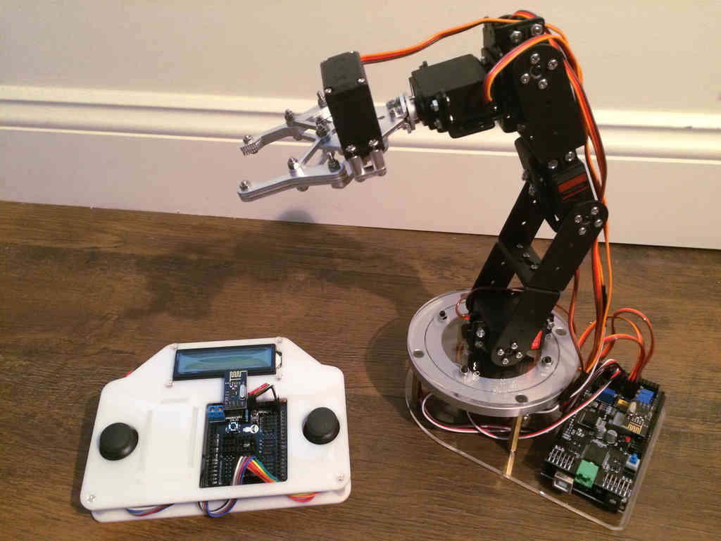
I ordered this 6 servo robotic arm kit, which is the only kit that includes the arm and electronics. The box contains the basic 6 servo robot arm (including gripper), an Arduino Mega 2560, and a Arduino Uno based remote controller. I wanted a complete package for my first arm, thus I choose this kit over buying individual parts.
I also ordered this rotatable platform, so that the arm and electronics could be based on a stable platform. I found this highly beneficial because the default metal base is tiny, often not providing enough stability for the arm when it is moving around.
The Arduino servo shield must be supplied with 12 volt DC power, which powers the servos. To handle this, I purchased this 12V at 0-2A AC to DC power plug. I had to cut off the end connector and strip the wires in order to secure them to the power connector on the shield. Alternatively, a variable DC power supply like this Tekpower 0-30V at 0-5A power supply would handle the job easily. I have not tested the exact power draw of the servos, but I think they use around 200mA in operation, thus a 2A power supply should be sufficient for the 6 servos and electronics.
These servo extension cables also came in handy, since the gripper servo cables don't reach the Arduino at the arm base.
Kit Expectations
Based on the Amazon reviews of this kit, I knew that the manufacturer did not provide much guidance on how to assemble or program the system. Many people are surprised by this lack of support, but I welcomed the uphill struggle. Instead of viewing the kit as a ready to run system, I considered it a rudimentary kit of pieces that should work together to eventually build a robotic arm.SainSmart does provide a brief YouTube video (with no audio...) of how the arm should be assembled, but it leaves a lot to be desired. I'd say it gets you 90% there, but it omits certain key aspects that make the process smoother. Some experimentation is still required when assembling the pieces.
Robot Arm Pieces
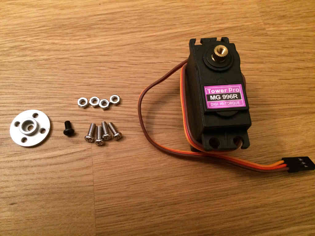
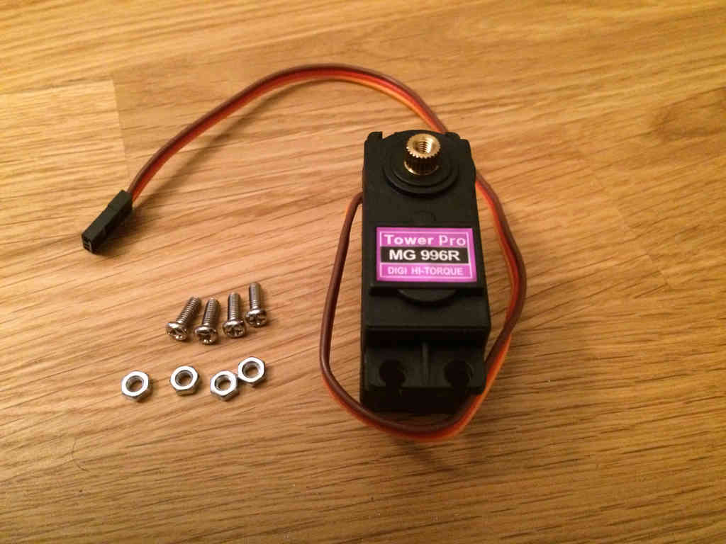
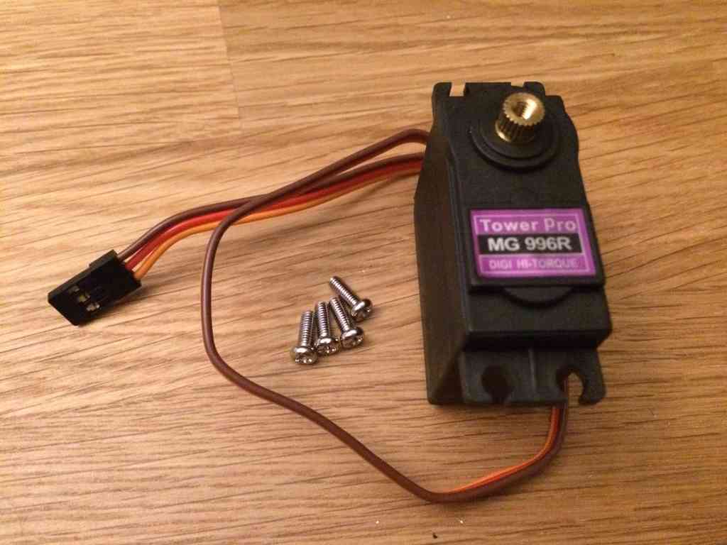
Here are all of the pieces that came with the robot arm: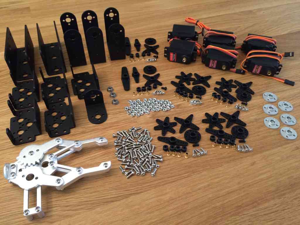 I liked this arm kit because it contained decently strong meta gear servos, including four MG 996R servos (11 kg-cm at 6v) and two DS3218 servos (~15 kg-cm at 6v).
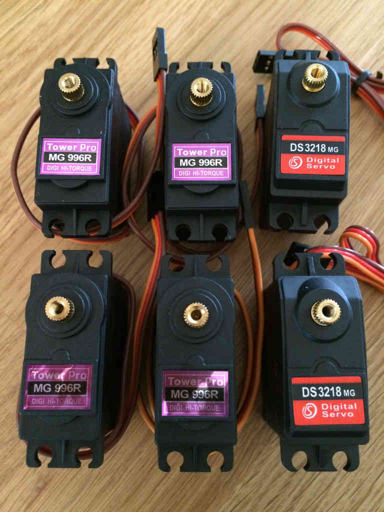 Surprisingly, the kit contains exactly all of the parts required. Well done SainSmart!
Pre-Build Steps
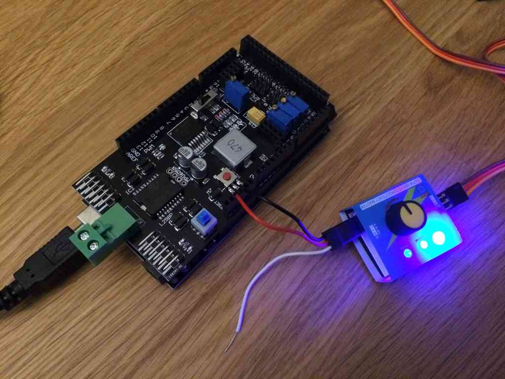
Before starting the build process, I think it is critical to test the servos and notate their neutral locations.I used a cheap servo tester to easily test each servo. To power the tester, I plugged in the positive and negative connectors into the Arduino's 5 volt and ground sockets. To power the Arduino, I plugged it into my computer via USB.
 I'd recommend using jumper wires
to connect the servo tester to the Arduino. At the time I didn't have
any, thus I had to cannibalize one of the servo extension cables I
bought.
I'd recommend using jumper wires
to connect the servo tester to the Arduino. At the time I didn't have
any, thus I had to cannibalize one of the servo extension cables I
bought.Robot Arm Build
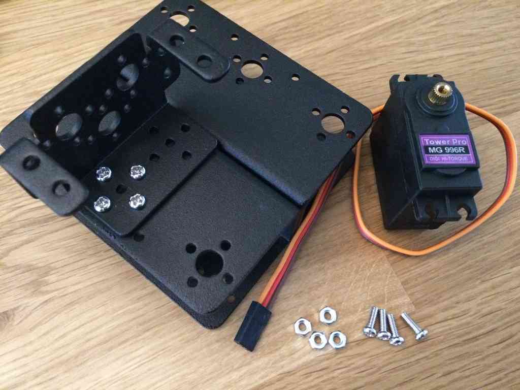
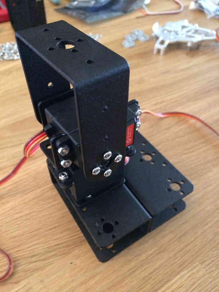
The following pictures follows the build process for the robot arm.First the robot base needs to be assembled.
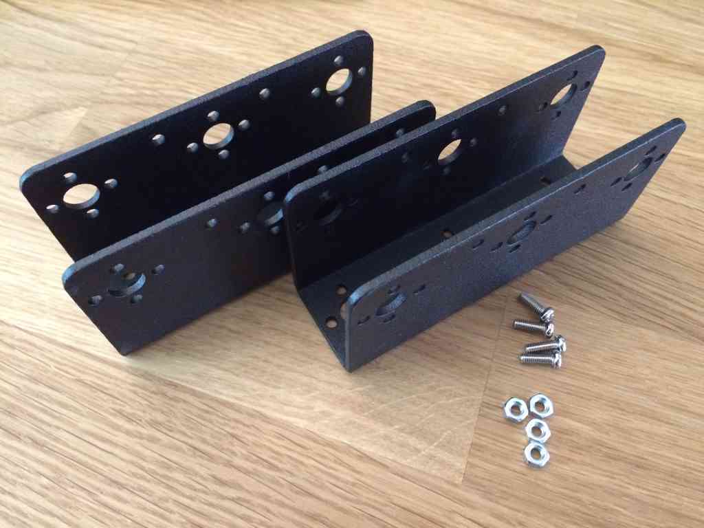
 This will allow the arm to rotate, acting as the arm's waist.
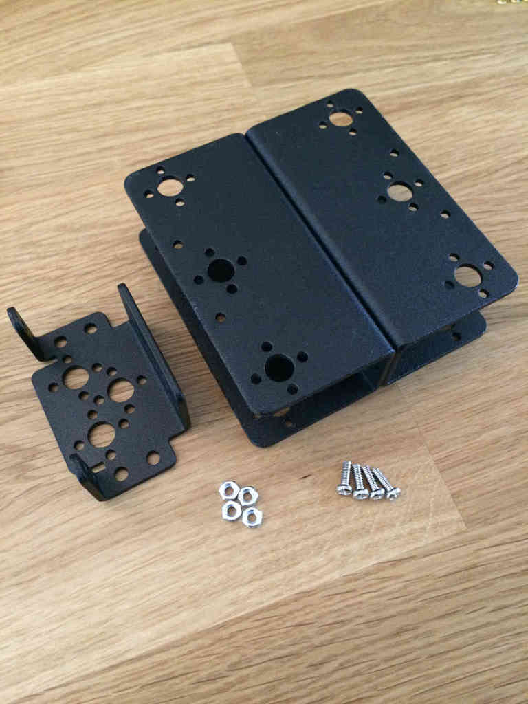
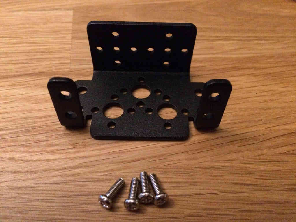
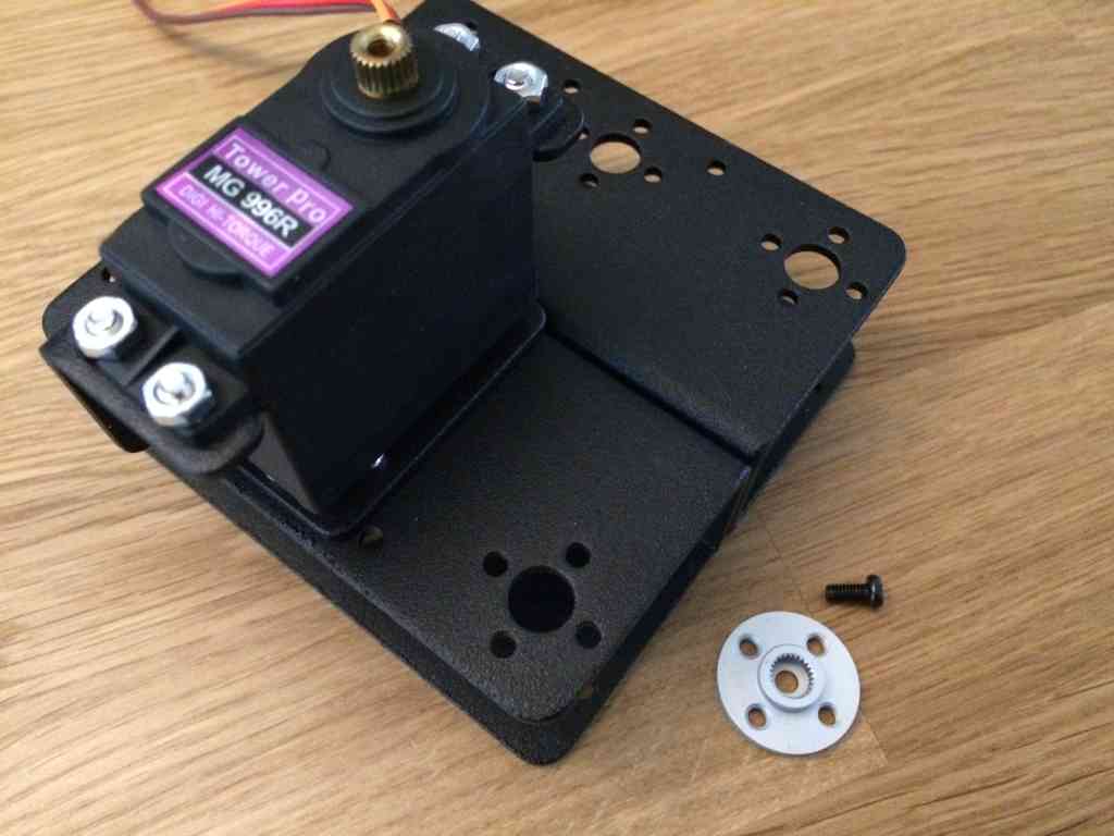 With the base complete, the arm can be started.
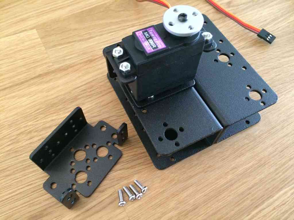
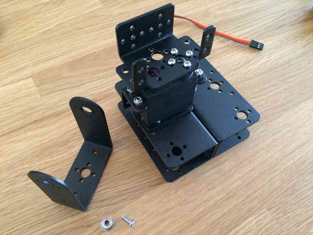
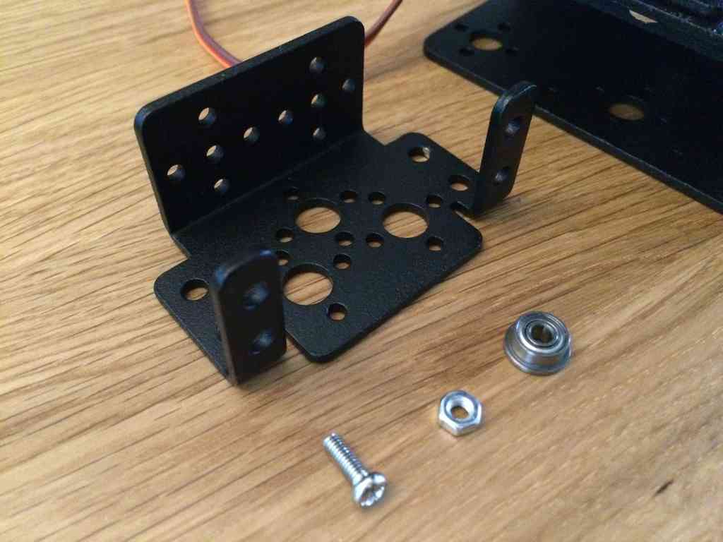
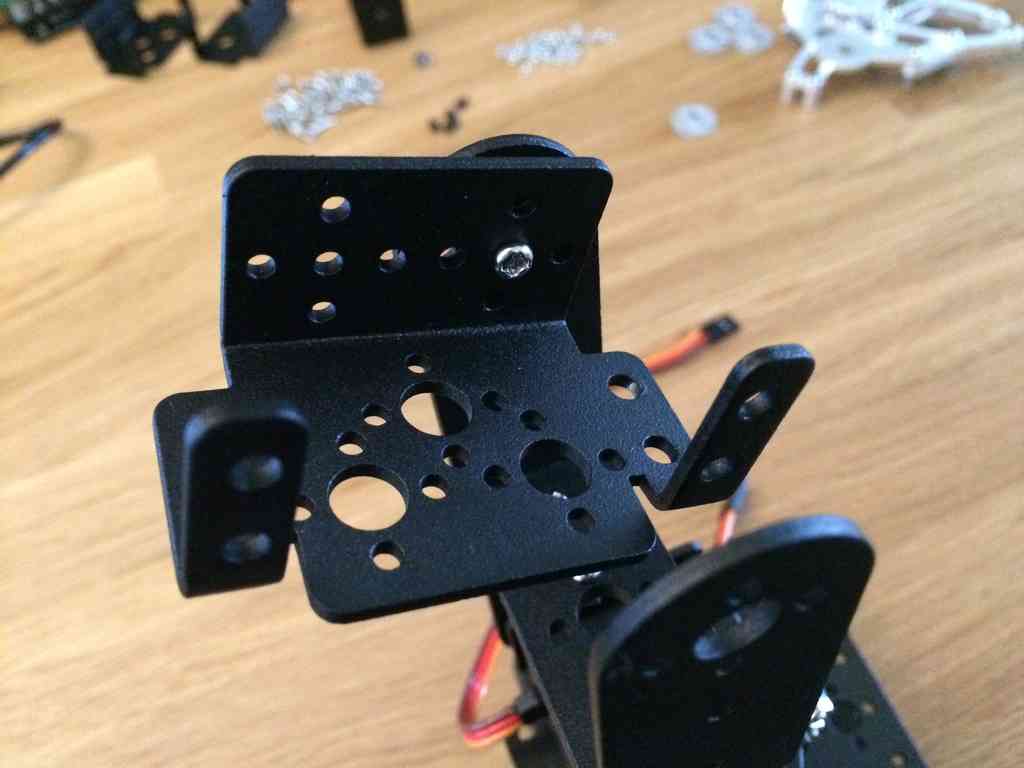
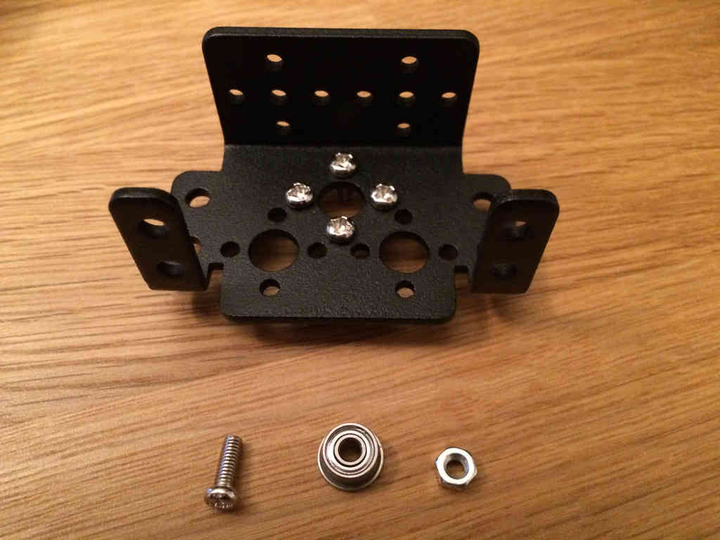
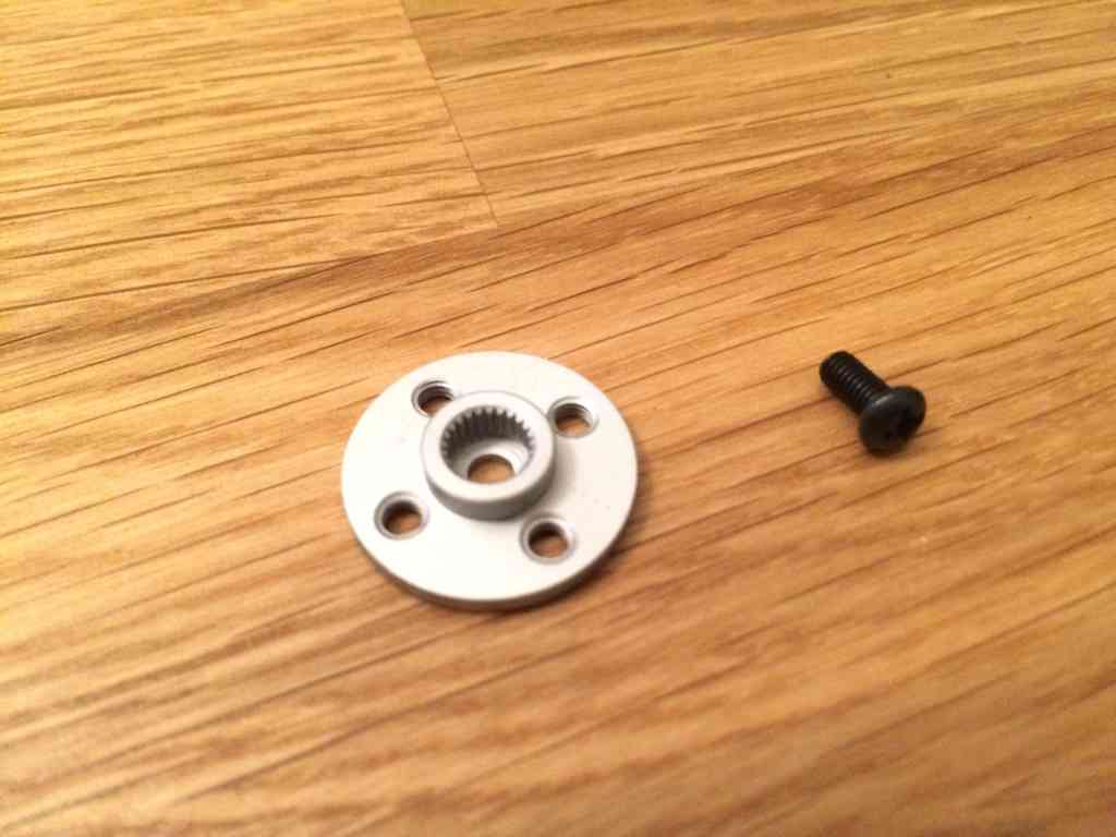
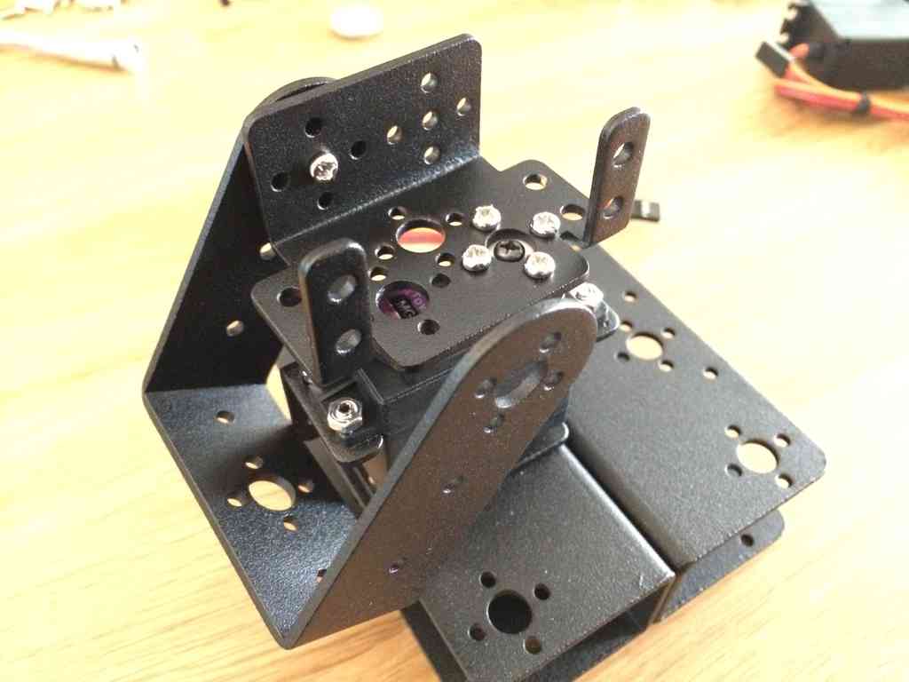 For these bearings, I placed the large flange between the static and
rotatable brackets. This will allow for some space between the two
moving pieces of frame.
For these bearings, I placed the large flange between the static and
rotatable brackets. This will allow for some space between the two
moving pieces of frame.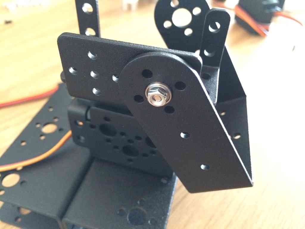
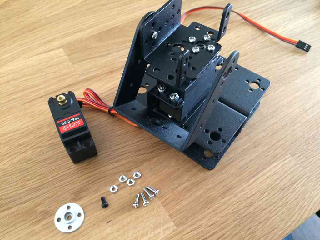
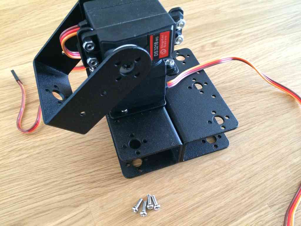
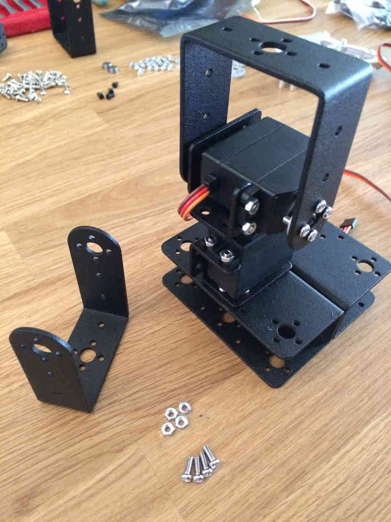
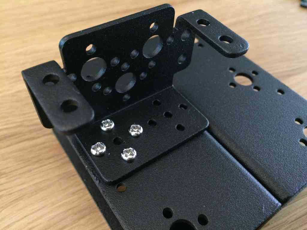
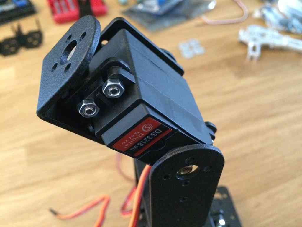
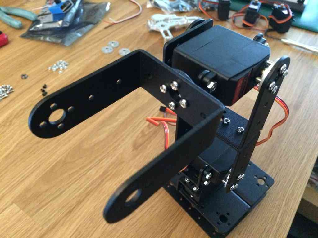
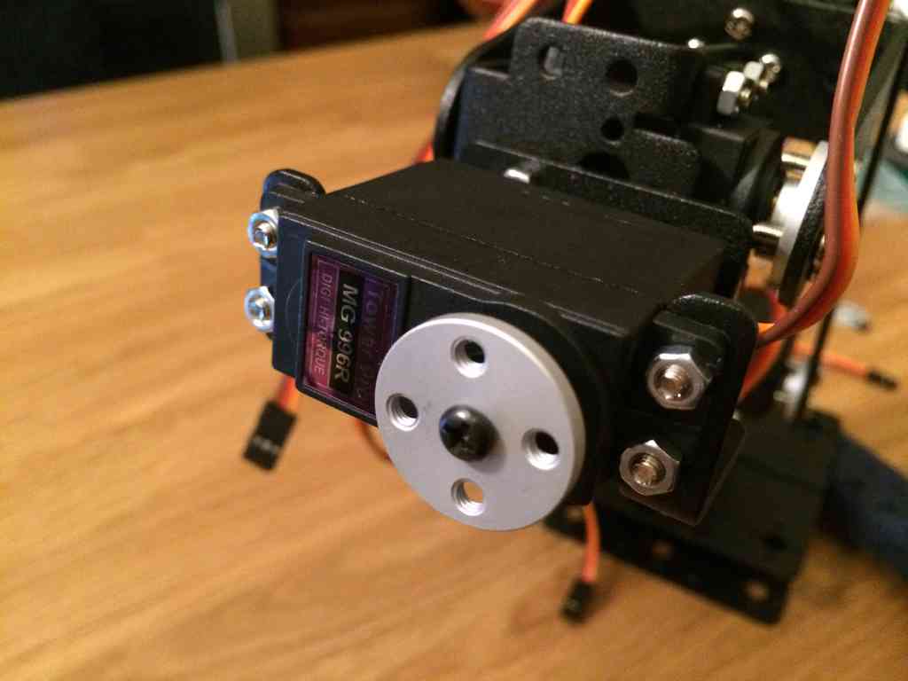
 The two lower arm servos use the stronger DS3218 servos. These servos
have the extra torque required to handle the weight of the gripper
mechanism.
The two lower arm servos use the stronger DS3218 servos. These servos
have the extra torque required to handle the weight of the gripper
mechanism.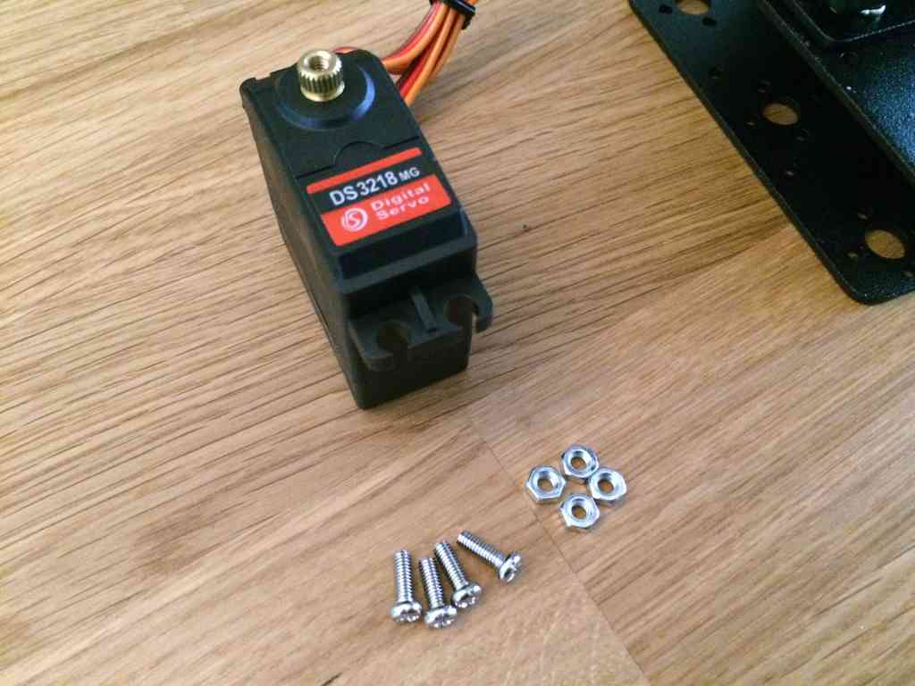
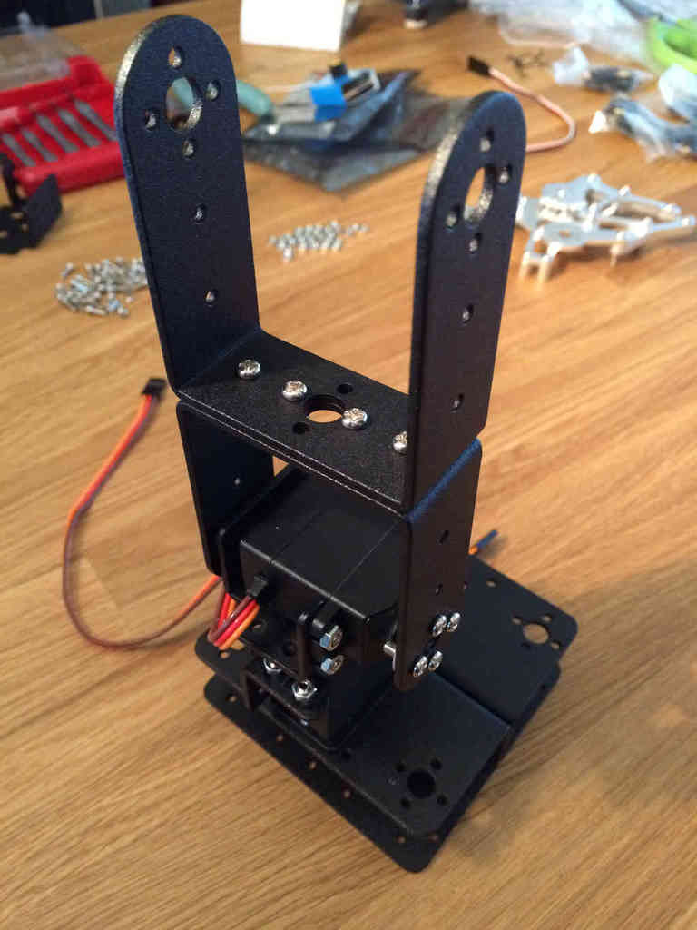
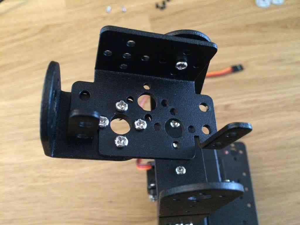
 Now to build the wrist mechanism. As I noted above, this arm does not
have a full spherical wrist since it omits the third elevation joint.
The wrist joints use the weaker MG 996R servos. For the wrist rotation
joint this is fine, however, I've noticed that the wrist elevation servo
strains to maintain some angles when it's outstretched.
Now to build the wrist mechanism. As I noted above, this arm does not
have a full spherical wrist since it omits the third elevation joint.
The wrist joints use the weaker MG 996R servos. For the wrist rotation
joint this is fine, however, I've noticed that the wrist elevation servo
strains to maintain some angles when it's outstretched.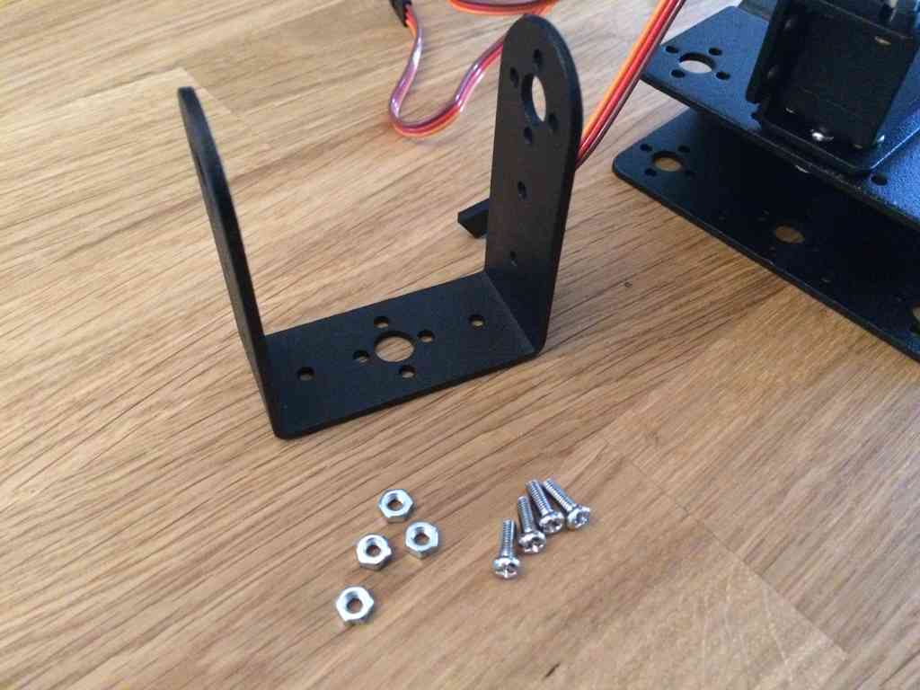
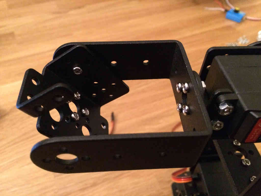
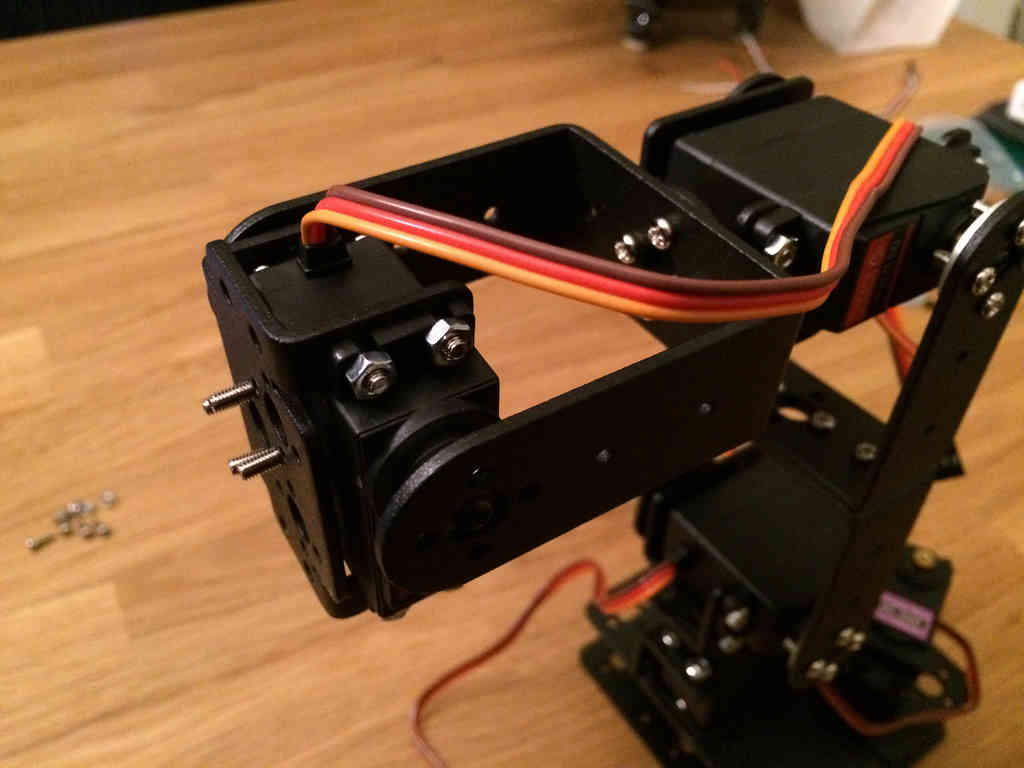
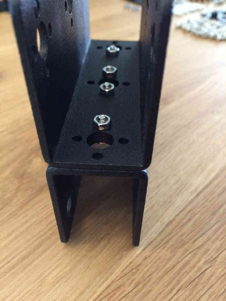
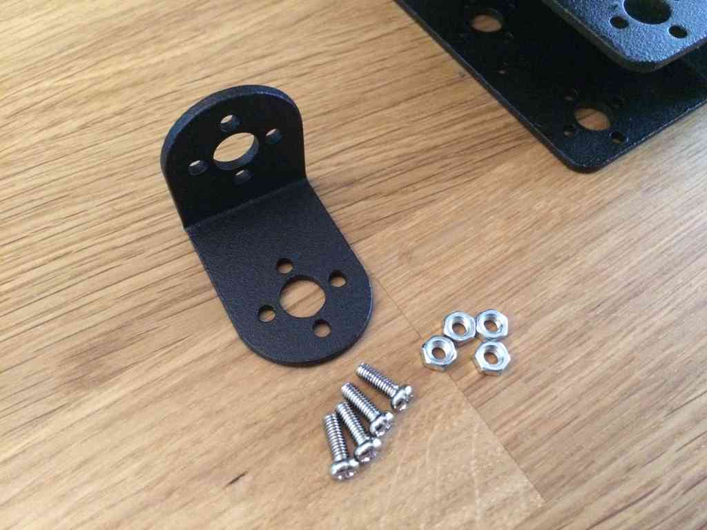
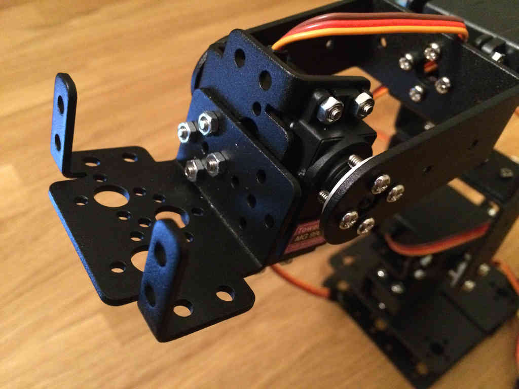
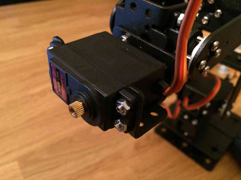
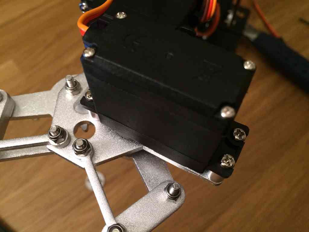
 Installing the bracket where the wrist rotation servo goes is tricky
because you cannot access the screw heads. Thus you will only be able to
secure the bracket by hand tightening the nuts. Time will tell if this
is enough to hold the nuts in place. The servo will prevent the nuts
from completely backing off, but that would create wobble in the
bracket.
Installing the bracket where the wrist rotation servo goes is tricky
because you cannot access the screw heads. Thus you will only be able to
secure the bracket by hand tightening the nuts. Time will tell if this
is enough to hold the nuts in place. The servo will prevent the nuts
from completely backing off, but that would create wobble in the
bracket.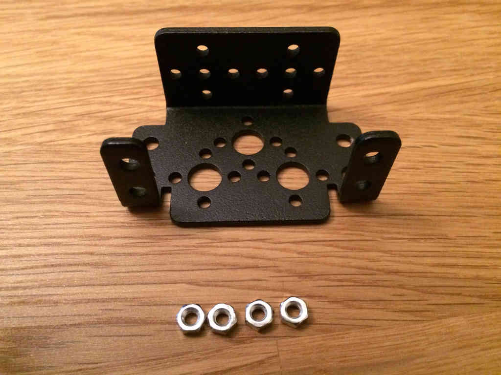
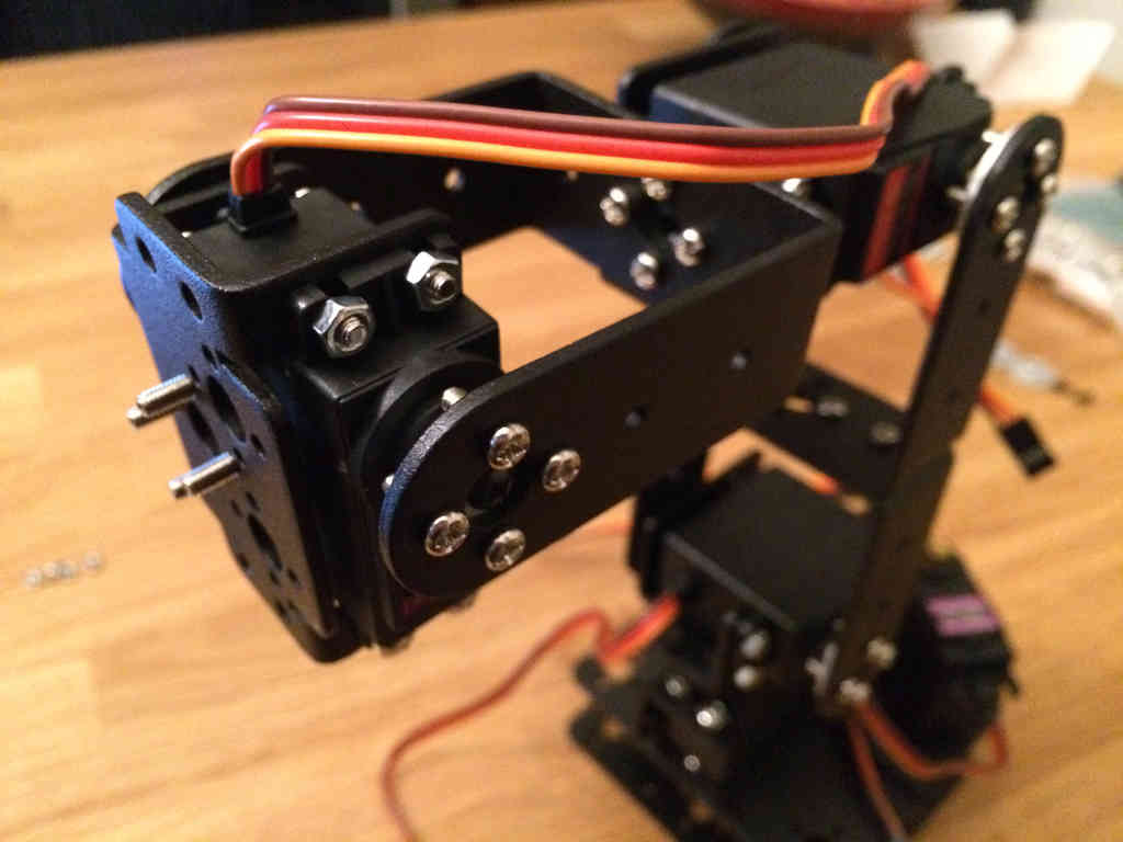
 The majority of the arm is built. Now the focus is on building the
gripper mechanism. Nearly all of the gripper's screws are loose, but
since they use locking nuts, this shouldn't be a problem. They do this
so that the gripper pieces can move freely around. Otherwise, each joint
would require a bearing which would be expensive. This causes some
wobble in the gripper fingers, but nothing too severe.
The majority of the arm is built. Now the focus is on building the
gripper mechanism. Nearly all of the gripper's screws are loose, but
since they use locking nuts, this shouldn't be a problem. They do this
so that the gripper pieces can move freely around. Otherwise, each joint
would require a bearing which would be expensive. This causes some
wobble in the gripper fingers, but nothing too severe.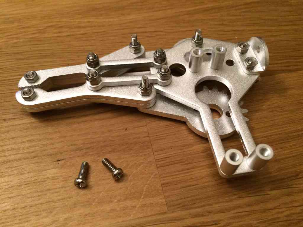
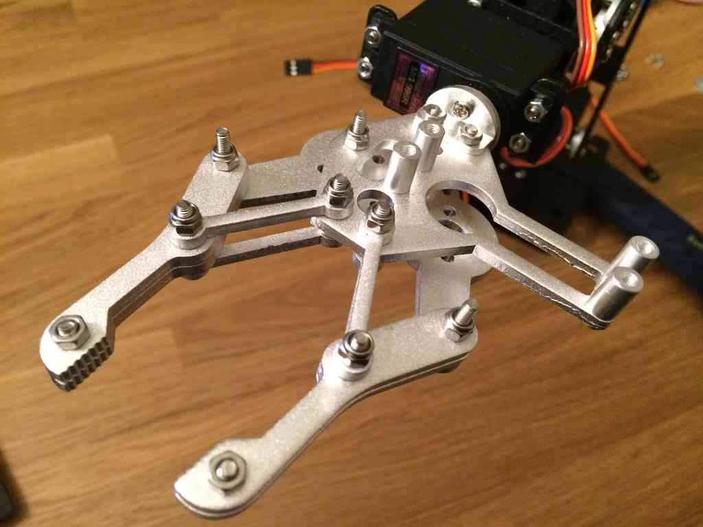
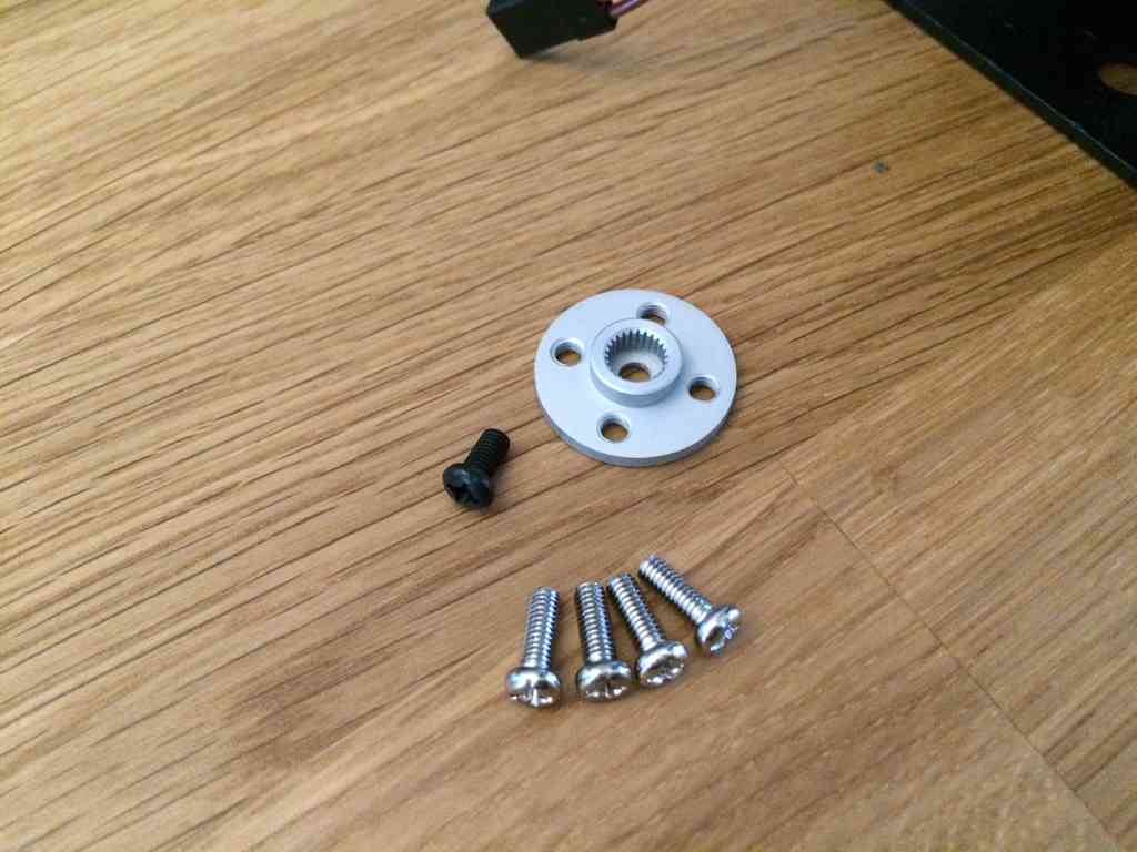
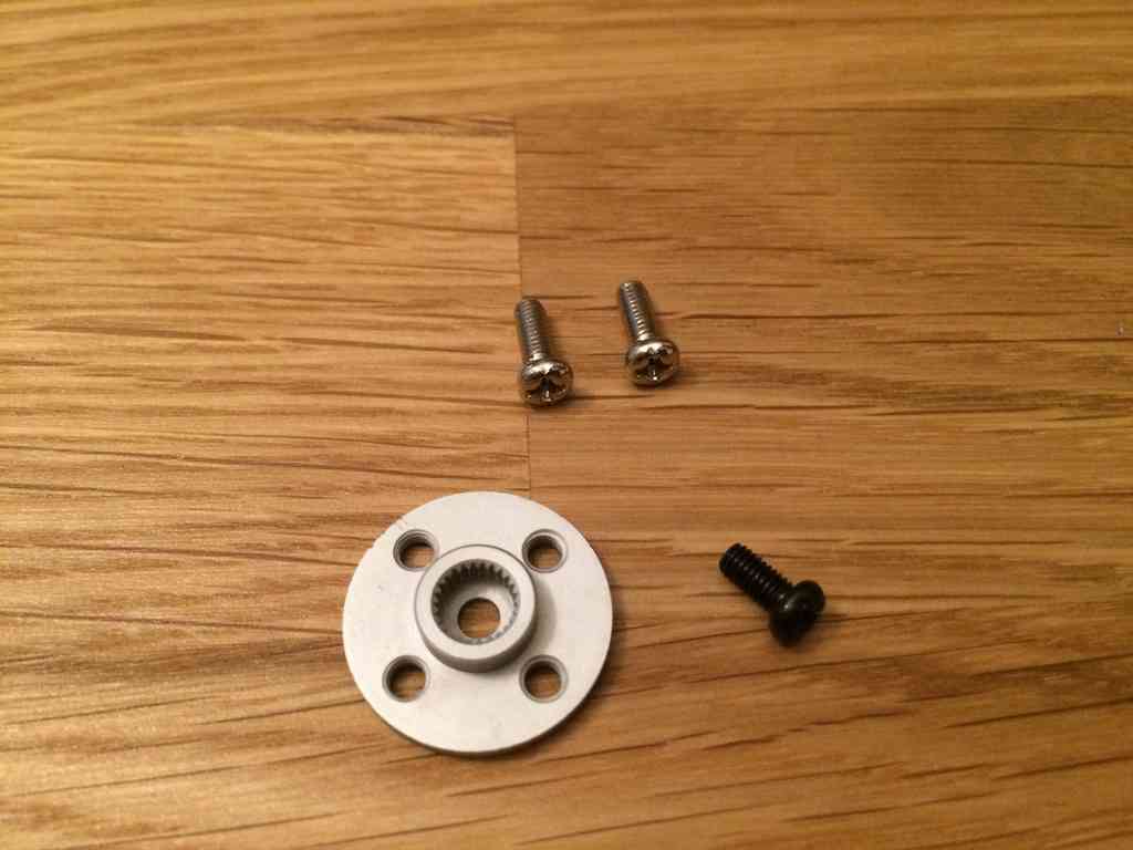 Slide in the servo horn between the gripper's base and left finger.
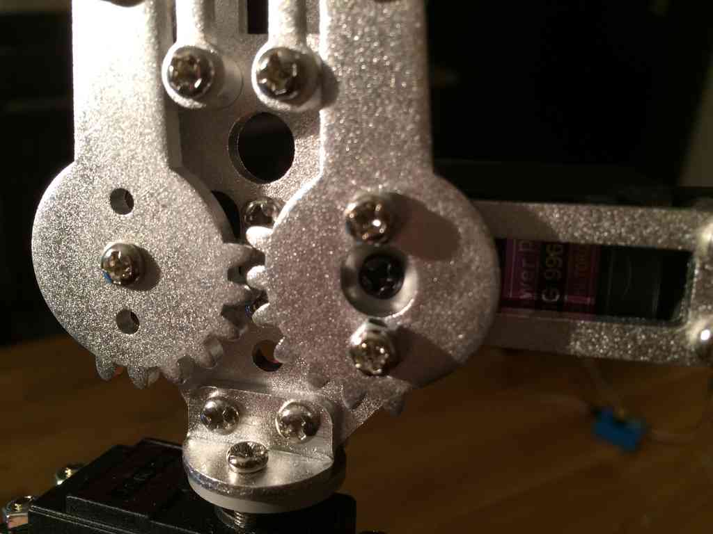
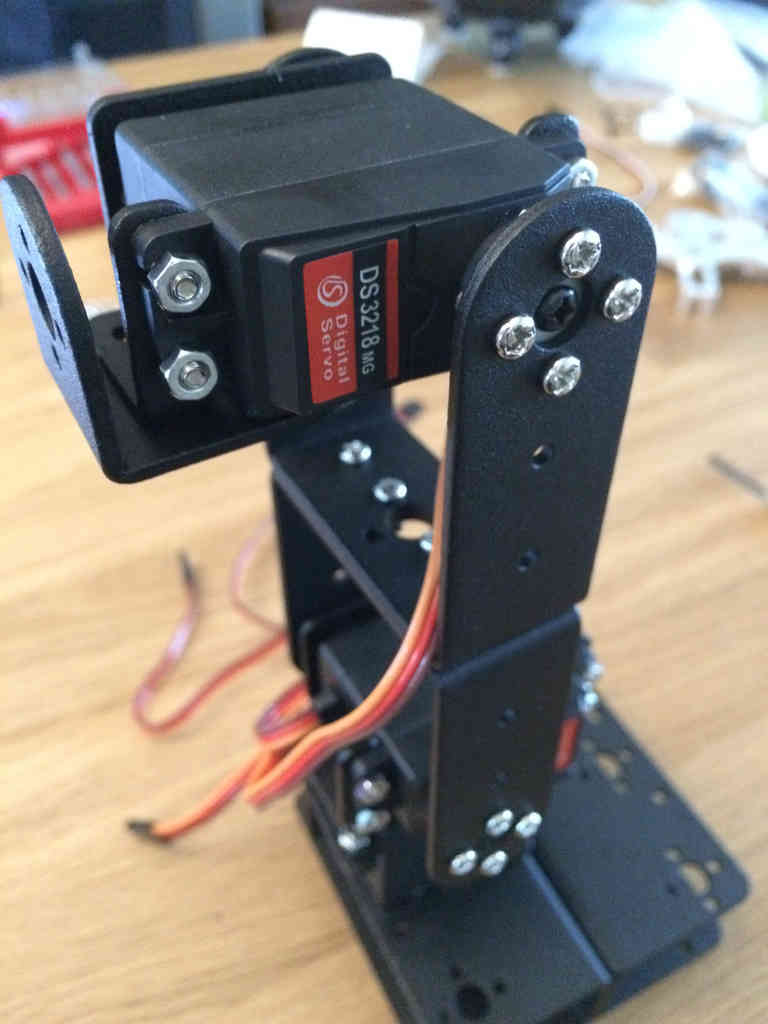
Finished Arm
The finished standard arm looks like this: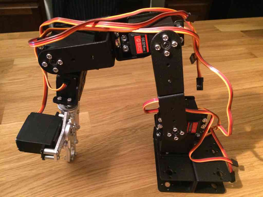 The metal base is sufficient for basic arm movements, but it is not
completely stable without some type of clamping mechanism. This is why
the optional SainSmart rotatable platform is a good addition!
The metal base is sufficient for basic arm movements, but it is not
completely stable without some type of clamping mechanism. This is why
the optional SainSmart rotatable platform is a good addition!Robot Arm Part 5: Basic Arm Code
Having finished building all parts of the robotic arm kit I bought (see part 1), it is now time to start programming the arm to make it do stuff. SainSmart provides a file with basic code, so I'll start with that.Provided File
SainSmart provides this large zip file (162 MB), which includes a video showing arm movement, a C++ script of basic arm commands, and a text file documenting the basics of the C++ script.The C++ script provides a basic idea for how to interact with the arm's servos. This code has some documentation, however, it's all in Mandarin.
The text file seems promising at first glance, but it assumes you are using an Arduino Uno, not the Mega the kit includes. It also only mentions the how of working with some of the code, not the why of the code structure.
Seeing that there is no hand holding from SainSmart, I had to debug the script line by line to learn its mysteries.
Code
After scanning the code, I realized that the code was not very good. I rewrote sections to provide better functionality with lots of documentation. All of the code below has been tested on my arm, however, many of the servo angles that work for my arm may not work for your arm due to the way you setup the servo horns when assembling the arm.You can find a complete copy of this script here.
The first section of the script is normal C++ code for including the Servo library, and for defining all variables.
#include <Servo.h>

Servo myservoA;
Servo myservoB;
Servo myservoC;
Servo myservoD;
Servo myservoE;
Servo myservoF;
int i, pos, myspeed, myshow;
int sea, seb, sec, sed, see, sef;
static int v=0;
static int mycomflag=2;
String mycommand="";void setup()
{
// Unsure what these do and if they are required
pinMode(13, INPUT);
pinMode(12, INPUT);
Serial.begin(9600); // Set the boud rate to 9600
mycomflag=1; // Default state of operation
// Attach each servo to a specific pin
myservoA.attach(11); // Waist servo at port 11
myservoB.attach(12); // Shoulder servo at port 12
myservoC.attach(13); // Elbow servo at port 13
myservoD.attach(8); // Wrist elevation servo at port 8
myservoE.attach(9); // Wrist rotation servo at port 9
myservoF.attach(10); // Gripper servo at port 10
// Position the waist in the center
myservoA.write(90);
// Position shoulder to a lower angle for better arm balance
myservoB.write(70);
// Position elbow to a higher angle for better arm balance
myservoC.write(140);
// Position the wrist elevation in the center
myservoD.write(90);
// Correct for a slight offset for the wrist rotation
myservoE.write(100);
// Default to a wide open gripper
myservoF.write(30);
}void loop()
{
// Set mycommand if a message is being entered into the serial port
while (Serial.available() > 0)
{
mycommand += char(Serial.read());
delay(2);
}
// If a command is provided, identify what it is before resetting it
if (mycommand.length() > 0)
{
if(mycommand=="#auto")
{
mycomflag=2;
Serial.println("auto station");
mycommand="";
}
if(mycommand=="#com")
{
mycomflag=1;
Serial.println("computer control station");
mycommand="";
}
if(mycommand=="#stop")
{
mycomflag=0;
Serial.println("stop station");
mycommand="";
}
}
// If performing computer control use this
if(mycomflag==1)
{
/* Calculate the new angle for the specific servo then move it there
Expect format of <int><alpha>
where <int> represents the servo angle between 0 and 180
and <alpha> represents the specific servo between a and f
For example, 90a moves servo a to 90 degrees, etc. */
for(int m=0; m<mycommand.length(); m++)
{
char ch = mycommand[m];
switch(ch)
{
/* When ch is between 0 and 9, calculate the servo angle
If there is an existing value for v, multiply it by 10 to put
it in the tens place, then put the second command value in the
ones place */
case '0'...'9':
v = v*10 + ch - '0';
break;
// Move waist
case 'a':
myservoA.write(v);
Serial.print("moving waist to ");
Serial.print(v);
Serial.println(" degrees");
v = 0;
break;
// Move shoulder
case 'b':
myservoB.write(v);
Serial.print("moving shoulder to ");
Serial.print(v);
Serial.println(" degrees");
v = 0;
break;
// Move elbow only if it's greater than 35 degrees
case 'c':
if(v >= 35) myservoC.write(v);
Serial.print("moving elbow to ");
Serial.print(v);
Serial.println(" degrees");
v = 0;
break;
// Move wrist elevation
case 'd':
myservoD.write(v);
Serial.print("elevating wrist to ");
Serial.print(v);
Serial.println(" degrees");
v = 0;
break;
// Move wrist rotation
case 'e':
myservoE.write(v);
Serial.print("rotating waist to ");
Serial.print(v);
Serial.println(" degrees");
v = 0;
break;
// Move gripper only between 30 and 90 degrees
case 'f':
if(v >= 30 || v <= 90) myservoF.write(v);
Serial.print("moving gripper to ");
Serial.print(v);
Serial.println(" degrees");
v = 0;
break;
}
}
mycommand="";
}
// If performing auto control, use this to cycle through these joint angles
if(mycomflag==2)
{
delay(3000);
Serial.println("starting auto mode");
// Cycle through the joint angle from specified start to end
myspeed=500;
for(pos=0; pos<=myspeed; pos+=1)
{
myservoA.write(int(map(pos, 1, myspeed, 90, 60)));
myservoB.write(int(map(pos, 1, myspeed, 70, 90)));
delay(1);
}
delay(1000);
myspeed=500;
for(pos=0; pos<=myspeed; pos+=1)
{
myservoA.write(int(map(pos, 1, myspeed, 60, 90)));
myservoC.write(int(map(pos, 1, myspeed, 140, 90)));
myservoD.write(int(map(pos, 1, myspeed, 90, 30)));
myservoE.write(int(map(pos, 1, myspeed, 100, 10)));
delay(1);
}
delay(1000);
myspeed=1000;
for(pos=0; pos<=myspeed; pos+=1)
{
myservoB.write(int(map(pos, 1, myspeed, 90, 50)));
myservoC.write(int(map(pos, 1, myspeed, 90, 150)));
delay(1);
}
delay(1000);
myspeed=500;
for(pos=0; pos<=myspeed; pos+=1)
{
myservoC.write(int(map(pos, 1, myspeed, 150, 120)));
myservoD.write(int(map(pos, 1, myspeed, 30, 140)));
myservoE.write(int(map(pos, 1, myspeed, 10, 100)));
myservoF.write(int(map(pos, 1, myspeed, 30, 85)));
delay(1);
}
delay(1000);
myspeed=1000;
for(pos=0; pos<=myspeed; pos+=1)
{
myservoA.write(int(map(pos, 1, myspeed, 90, 140)));
myservoF.write(int(map(pos, 1, myspeed, 85, 30)));
delay(1);
}
delay(1000);
myspeed=500;
for(pos=0; pos<=myspeed; pos+=1)
{
myservoA.write(int(map(pos, 1, myspeed, 140, 90)));
myservoB.write(int(map(pos, 1, myspeed, 50, 70)));
myservoC.write(int(map(pos, 1, myspeed, 120, 140)));
delay(1);
}
delay(1000);
}
// No command was specified
if(mycomflag==0)
{
Serial.println("no mode specified; use either #com or #auto");
}
}Running the Code
To run this script, first open the file within the Arduino IDE. You can view and edit the code within this window. Next specify the correct board you are using within Tools > Board > Arduino Mega 2560. Select the correct device within Tools > Serial Port > /dev/ttyACM0.Now you can upload the script to the Arduino by pressing the Upload button on the toolbar or select File > Upload.
Note that once uploaded, the Arduino will execute the program immediately. If you are using the Arduino servo shield, the servos will not start moving until the shield is connected to a 12 volt DC power input, and the power button is pressed down.
Open the serial monitor by selecting Tools > Serial Monitor, or pressing Ctrl+Shift+m. You will be able to send commands to the Arduino via the serial monitor. To make the arm use auto control, type #auto. To use the computer control, type #com.
When using computer control, you can specify specific joint angles by typing the angle (integer between 0 and 180) and joint identifier (a - f) into the serial monitor. For example, typing 90b will move the second joint (shoulder) to 90 degrees. Typing 90f will close the gripper while typing 30f will open the gripper as wide as it can go. Again, these angles work with my servos, but you may have angled you servos at different orientations, thus make sure to test the limits of each servo before moving them to extreme angles.
Next
This basic script does a good job at showing how to work with the arm. I think it illustrates just how easy it is to work with these servos.Next I want to expand the capability of what the file can do. I also want to explore how to integrate the remote controller with the arm, so that I can control the arm using the joysticks on the controller. That will require programming the controller's Arduino Uno to talk with the arm's Arduino using the 2.4 Ghz radios. Stay tuned for that!


0 Comments